
Overview
I have been fascinated for the last few years with wearables….especially watches and after seeing Chronio on Hackaday I decided to give it a try myself.
Before I continue let me put a shout out the following projects and resources used heavily in developing the watch.
Zak Kemble DIY Digital Wristwatch – Inspiration and software.
Chronio – Watch design and low power design.
Mattairtech – Board programming environment and Bootloader.
Adafruit – Software libraries and years of electronics inspiration.
Prototyping
The Chronio display (Sharp Memory) is no longer available so I am going to upgrade to a larger display and with that a processor with more memory to handle the larger display. I also wanted to continue to run this from a CR2032 coin cell battery so I needed a processor that would consume little power when sleeping.
I decided to go with the ATSAMD21E18 processor from Microchip for a few reasons. First I am familiar with Atmel range of chips. Second, a larger Flash (256KB) and SRAM (32KB). Third, it is Arduino compatible and has plenty of library support and can be programmed using the Arduino IDE and fourth, it has USB 2.0 Interface builtin. Can be program via USB with an installed boot loader.
Researching SAMD21 development boards to prototype my watch I came across Mattairtech. He has some really well designed development boards at great prices. He also has great documentation and Arduino board managers that can be added to Arduino IDE.
I bought a MTD21E Revision B from Mattairtech and started my prototyping.
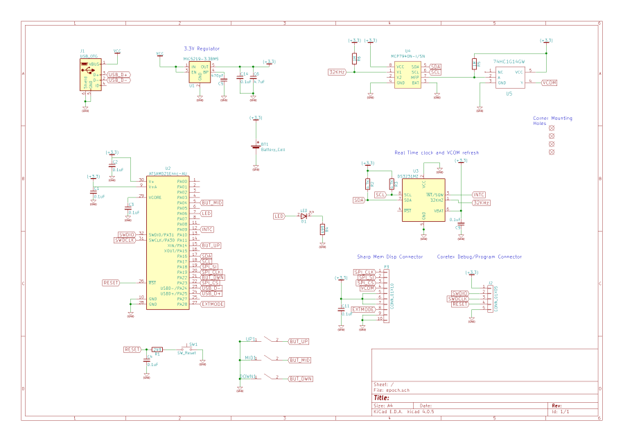
Schematic
Below is the schematic for my watch. A couple of things to notice. First no crystal/oscillator is used for the ATSAMD21E18 as I used the internal oscillator. Second No crystal is needed for the MCP7940M RTC as I can feed the 23Khz signal from the DS3231M into MCP7940M as the clock feed. Again this means I do not need a crystal for the MCP7940M, reducing the part count. schematic PDF.
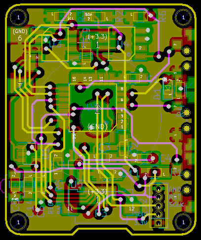
Circuit Board
3D Printed parts
3D printed parts designed in Autodesk Fusion 360.
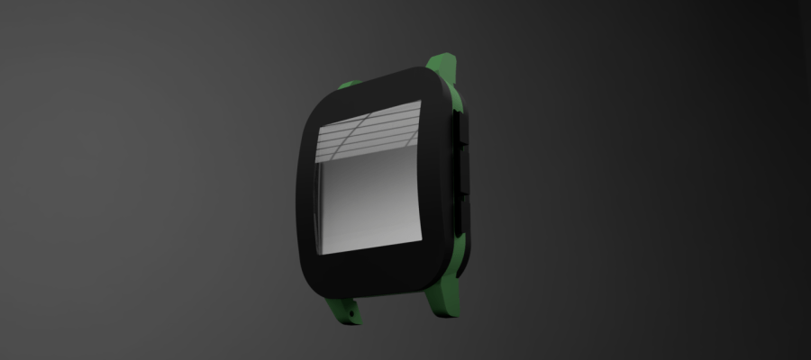
Animation is shown below:
Software
Developed in C/C++ using Adafruit graphics and memory display library. Hard part was getting the power consumption the lowest possible. When using Arduino IDE you are using Wiring, an open-source protyping platform. The processor initialization done as part of the Wiring startup and caused me problems when trying to put the processor into deep sleep whilst reducing the power consumption. I could not get it below 5mA when in deep sleep which is way higher than the 5uA it is supposed to be at.
A month of evening playing with the initialization code I tracked down the problem to the tick timer used by functions such as milli(). This has to be disabled before entering deep sleep and enable after waking up from deep sleep.
BOM
Coming soon
Putting it all together
Finished product sample pictures


First Problem
A good quality CR2032 voltage dropped to 2.7V after 10 days and the display no longer worked. Min spec for display is 2.7V.
Design Update to add Boost Converter
To keep the voltage at 3.3V for a longer period I decided to use a boost converter that works down to 1.8V. Adding this no gives approx 3 weeks before battery finally gave up.
I have decided to use a chargeable LIPO battery for my next version.
